About this deal
I have that model, too. That board is a mistake by design. It was very infuriating to find out the power supply was changing, while the levels on the data pins voltage were always 0..5V. http://kiguino.moos.io/2014/12/31/how-to-use-arduino-nano-mini-pro-with-CH340G-on-mac-osx-yosemite.html This is a simple guide that will teach you how to take the first steps with the BTE13-010 module, a cheap Arduino mini clone. We will go through the 4 basic steps necessary to get it working immediately and without problems: keeping, as already mentioned, the Arduino inserted on the two connectors, solder the 4 pads in the corners. Why only these 4 points? Because the breadboard is made of plastic and excessive heat could damage it
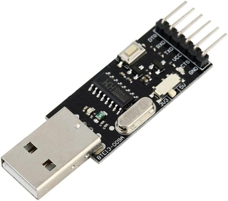
I am a hobbyist, not an EE, with about a dozen Linux SBCs and a half a dozen WiFi switches and access points, two of them in active use running OpenWRT. An Odroid HC1 I have has an UART at 1.8V logic levels; it is probably the most ornery one I have. I need 1.8V and 3.3V, and occasionally find that 2.8V-3.0V and 3.8-4V would also be useful, so basically I want "whatever the device uses, between 1.6 and 5.3 V" or so. Look at the Fritzing diagram above or follow the instructions below to connect the Arduino mini clone to the Serial to USB converter: BTE13-010--------------CH340G Be careful not to connect the TXD terminal of the BTE13-010 with the TXD terminal of the CH340G (or the two RDX terminals)! To find out why, read this clear guide from Sparkfun on serial port operation and connection. But it doesn’t end here! That’s were the Power Cutter comes in. Thanks to Talpa PCB retrace of the BTE13-010 I was able to elaborate an evil power saving plan: The power_saving_init() should be the first thing to be called at setup(), it will initialize all your pins to LOW. power_saving_sleep() will put everything to sleep, and wake up every 8 seconds. With these two, with the regular board (no bootloader modifications, with the power regulator on, etc) when sleeping I was able to achieve 3.24mA of power consumption, which is already pretty good considering it was draining about 10.2mA when fully powered on in the first place.The first one I killed when I used a USB TTL adapter that I believe kept the TTL signal level at 5V even when selecting 3.3V. As long as your computer can see other devices plugged into the same USB port and assigns them a comm port number (each number is unique to THAT device) then it is either the cable or the board on the Ortur. We specify that this procedure works with devices that already have a bootloader installed inside them. We have never loaded a bootloader but on the Internet there are many tutorials on the subject, such as: So my first idea was to buy a (maybe isolated) USB adapter and putting it in a heavy enclosure with a selection switch that makes it very obvious the voltage was.
However, if you look at the CH340 datasheet, the same board can be modified to change both the Vcc and the data pins voltage from the same switch, but you'll have to cut a few traces and rewire. I modified mine, but can not find the schematic with the changes right now. It was only a few traces to rewire as seen in the pics, and now it switches both the power and the data levels. Often the FTDI based ones are preferred. The FTDI chip is very expensive in comparison with other USB to TTL bridges, but they are often preferred. So look for FTDI when searching USB to TTL. Often FTDI ones use fake clones instead of the genuine and expensive FTDI, so if it's too cheap then it's probably not genuine FTDI. Simply put…the computer is not even seeing anything plugged into the comm port. trying to do any more communication is pointlesss. Like not getting a dial tone on a phone…trying to continually dial out is an effort in futility.
Our sketch is based on the one found by default on the IDE and which is called “Sweep”, with the addition of a 16×2 LCD display that shows the value of the rotation angle of the servo. Basically, it rotates the servo and shows how much it rotated on the display. Another alternative is to buy the FTDI chip from a reliable vendor, so to be sure it is genuine, then wire your own. Here's an example of a FT232RL wired by hand to a 0.1 inch perfboard. As said you can try rebooting your computer and see if that helps…I never had to myself for my diode laser but…I have had to for other driver installs so…can’t hurt. Computers are funny things.
the operation can be made simpler and more precise with the help of a breadboard. Insert the connectors into the breadboard so that they are perfectly vertical and place the Arduino on them If you buy your own FTDI chip, go for something that has two serial ports, e.g. FTDI FT2232H, those are often used as JTAG interface with an additional serial port, too. I wanted to hide the USB serial and USB sound dongles in the box so I looked through my junk box for a USB Hub. I found a 4 port hub so I decided to add a USB memory key. Then I saw level shifter like a TXB0104 - would that be something where I could simply connect RX/TX/VCC/GND on both sides and turn my brain off?Before connecting the Serial – USB converter, make sure that the switch is positioned on the appropriate voltage value which can be 3.3V or 5V depending on the model of your Arduino. Ours works at 5V and 3.3V interchangeably. Arduino clones need specific drivers, different from the standard ones that come with the Arduino IDE
 Great Deal